
Hexadecimal and Numeric
Indicators
Technical Data
5082-7300
5082-7302
5082-7304
5082-7340
Features
• Numeric 5082-7300/-7302
0-9, Test State, Minus Sign,
Blank States
Decimal Point
7300 Right Hand D.P.
7302 Left Hand D.P.
• Hexadecimal 5082-7340
0-9, A-F, Base 16 Operation
Blanking Control, Conserves
Power
No Decimal Point
• DTL/TTL Compatible
• Includes Decoder/Driver with
5-Bit Memory
8421 Positive Logic Input
• 4 x 7 Dot Matrix Array
Shaped Character, Excellent
Readability
• Standard Dual-in-Line
Package Including Contrast
Filter
15.2 mm x 10.2 mm (0.6 inch
x 0.4 inch)
• Categorized for Luminous
Intensity
Assures Uniformity of Light
Output from Unit to Unit
within a Single Category
Description
Agilent’s 5082-7300 series solid
state numeric and hexadecimal
indicators with on-board decoder/
driver and memory provide 7.4 mm
(0.29 inch) displays for reliable,
low-cost methods of displaying
digital information.
The 5082-7300 numeric indicator
decodes positive 8421 BCD logic
inputs into characters 0-9, a “–”
sign, a test pattern, and four
blanks in the invalid BCD states.
The unit employs a right-hand
decimal point.
Package Dimensions
FUNCTION
5082-7300
and 7302
NUMERIC
5082-7340
HEXADECIMAL
PIN
1
2
3
4
INPUT 2
INPUT 4
INPUT 8
INPUT 2
INPUT 4
INPUT 8
BLANKING
CONTROL
NOTES:
1. DIMENSIONS IN MILLIMETERS
AND (INCHES).
2. UNLESS OTHERWISE SPECIFIED,
THE TOLERANCE ON ALL
DIMENSIONS IS ± 0.38 mm
(± 0.015 INCH).
3. DIGIT CENTER LINE IS ± 0.25 mm
(± 0.01 INCH) FROM PACKAGE
CENTER LINE.
GROUND
V
CC
INPUT 1
LATCH
ENABLE
5
6
7
8
GROUND
V
CC
INPUT 1
LATCH
ENABLE
DECIMAL
POINT
14.0
(0.55)
10.2 MAX.
(0.400)
4.8
(0.19)
7.4
(0.29)
1.5
(0.06)
5082-7300
14.0
(0.55)
10.2 MAX.
(0.400)
4.8
(0.19)
7.4
(0.29)
1.5
(0.06)
5082-7302
14.0
(0.55)
10.2 MAX.
(0.400)
4.8
(0.19)
7.4
(0.29)
1.5
(0.06)
5082-7340
3.0
(0.12)
5° 5° 5°
5.6
(0.22)
5.6
(0.22)
3.6
(0.14)
10.2
(0.400)
5082
7300
YYWW
X
LUMINOUS
INTENSITY
CATEGORY
DATE CODE
PIN 1 KEY
5678
4321
15.2
(0.600)
4.3
(0.17)
2.8
(0.11)
0.3 ± 0.08 TYP.
(0.012 ± 0.003)
0-10°
SEATING
PLANE
3.4
(0.135)
2.5 ± 0.13 TYP.
(0.10 ± 0.005)
3.8
(0.15)
1.3 TYP.
(0.050)
1.5
(0.06)
SEATING
PLANE
0.5 ± 0.08 TYP.
(0.020 ± 0.003)

2
The 5082-7302 is the same as the
5082-7300, except that the
decimal point is located on the left-
hand side of the digit.
The 5082-7340 hexadecimal
indicator decodes positive 8421
logic inputs into 16 states, 0-9 and
A-F. In place of the decimal point
an input is provided for blanking
the display (all LEDs off), without
losing the contents of the memory.
Applications include terminals and
computer systems using the base-
16 character set.
The 5082-7304 is a (± 1)
overrange display including a right-
hand decimal point.
Applications
Typical applications include point-
of-sale terminals, instrumentation,
and computer systems.
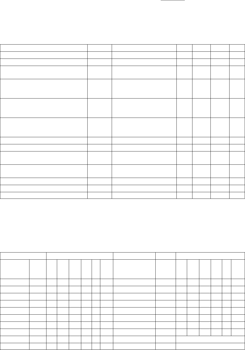
Absolute Maximum Ratings
Description Symbol Min. Max. Unit
Storage Temperature, Ambient T
S
-40 +100 °C
Operating Temperature, Case T
C
-20 +85 °C
V
CC
Pin Potential to Ground Pin V
CC
-0.5 +7.0 V
Voltage Applied to Input Logic Pins and Decimal Point
[1]
Voltage Applied to Latch Enable V
E
-0.5 +5.5 V
Voltage Applied to Blanking Control
[2]
V
B
-0.5 +5.5 V
Notes:
1. Decimal point applies only to 7300/7302.
2. Applies only to 7340.
Recommended Operating Conditions
Description Symbol Min. Nom. Max. Unit
Supply Voltage V
CC
4.5 5.0 5.5 V
Logic Voltage “0” State V
IN(0)
0 0.8 V
Logic Voltage “1” State V
IN(1)
2.0 5.25 V
Latch Enable Voltage – Data Being Entered V
E(0)
0 0.8 V
Latch Enable Voltage – Data Not Being Entered V
E(1)
2.0 5.25 V
Blanking Control Voltage – Display Not Blanked
[1]
V
B(0)
0 0.8 V
Blanking Control Voltage – Display Blanked
[1]
V
B(1)
3.5 5.25 V
Note:
1. Applies only to 7340.
3
Electrical/Optical Characteristics (T
A
= -20°C to +85°C, Unless Otherwise Specified)
Description Symbol Test Conditions Min. Typ. Max. Unit
Supply Current I
CC
V
CC
= 5.5 V 94
[1]
170
[2]
mA
Power Dissipation P
T
V
CC
= 5.5 V 470
[1]
935
[2]
mW
Luminous Intensity per LED I
V
V
CC
= 5.5 V, T
C
= 25°C3270 µcd
(Digit Average)
[3]
Minimum Time Data Must Be t
SETUP
V
CC
= 5.0 V, V
E(0)
= 0.4 V 30 50 ns
Presented to Logic Input Prior V
IN(0)
= 0.4 V, V
E(1)
= 2.4 V
to Enable Rising V
IN(1)
= 2.4 V, T
C
= 25°C
Minimum Time Data Must Be t
HOLD
V
CC
= 5.0 V, V
E(0)
= 0.4 V 30 50 ns
Held After Enable Rises V
IN(0)
= 0.4 V, V
E(1)
= 2.4 V
V
IN(1)
= 2.4 V, T
C
= 25°C
Time Required for 90% Change t
BLANK
V
CC
= 5.0 V, T
C
= 25°C 500 ns
in Display Luminous Intensity
After Change of State of F
B
[4]
Blanking Control Current “0” State
[4]
I
B(0)
V
CC
= 5.5 V, V
B(0)
= 0.8 V 200 µA
Blanking Control Current “1” State
[4]
I
B(1)
V
CC
= 5.5 V, V
B(1)
= 4.5 V 2.0 mA
Logic and Latch Enable I
IN(0)
,V
CC
= 5.5 V -1.6 mA
Currents “0” State I
E(0)
V
IN
, V
E
= 0.4 V
Logic and Latch Enable I
IN(1)
,V
CC
= 5.5 V +250 µA
Currents “1” State I
E(1)
V
IN
, V
E
= 2.4 V
Peak Wavelength λ
PEAK
T
C
= 25°C 655 nm
Spectral Halfwidth ∆λ
1/2
T
C
= 25°C30nm
Weight 0.8 gm
Notes:
1. V
CC
= 5.0 V with statistical average number of LEDs lit.
2. Worst case condition excluding test state on 5082-7300/-7302.
3. The digits are categorized for luminous intensity such that the variation from digit to digit within a category is not discernible to the
eye Intensity categories are designated by a letter located on the reverse side of the package contiguous with the Agilent logo
marking.
4. Applies only to -7340.
Truth Table for 5082-7300 Series Devices
Character Input Character Inputs
5082- 5082- 5082- 5082-
7300/7302 7340 7300/7302 7340
Numeric Hex. X8 X4 X2 X1 E B
[1]
Numeric Hex. X8 X4 X2 X1 E B
[1]
0 0 L L L L L Test A H L H L L L
1 1 L L L H L L Blank B H L H H L L
2 2 L L H H L L Minus D H H L H L L
3 3 L L H H L L Minus D H H L H L L
4 4 L H L L L L Blank E H H H L L L
5 5 L H L H L L Blank F H H H H L L
6 6 L H H L L L Hold Hold d d d d H d
7 7 L H H H L L – Blank
[1]
d d dddH
8 8 H L L L L L Decimal pt. on
[2]
–DP
IN
= L
9 9 H L L H L L Decimal pt. off
[2]
–DP
IN
= H
Notes:
1. The blanking control input, B, pertains to the 5082-7340 Hexadecimal Indicator only.
2. The decimal point input pertains to the 5082-7300 and -7302 Numeric Indicators only.
3. H = logic ‘1’; L = logic ‘0’; d = ‘don’t care.’


.jpg "RT-02T-1.3B(LF)")


