15815509278
取消

141150

  • 141150
  • 141150
141150
CIRCUIT BREAKER
Optifuse
TYPE I 42VDC 1
-
YES
© KEMET Electronics Corporation, P.O. Box 5928, Greenville, S.C. 29606, (864) 963-630020
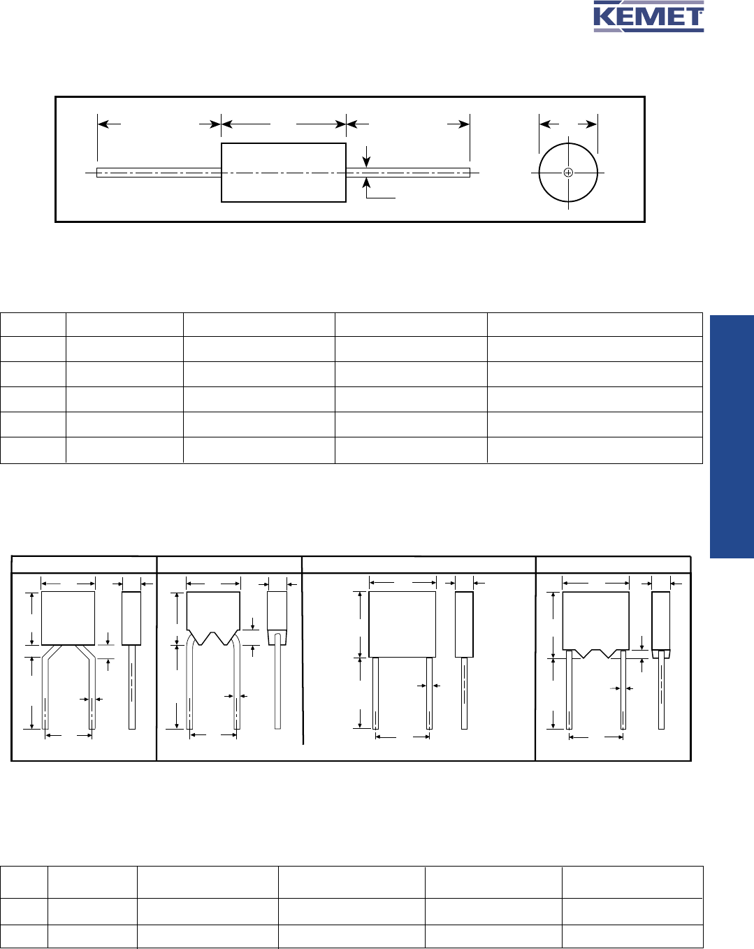
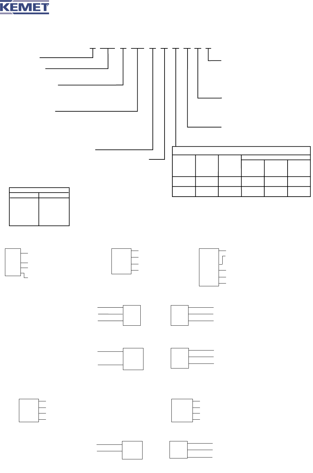
CERAMIC MOLDED AXIAL & RADIAL
PERFORMANCE CHARACTERISTICS
GENERAL
Working Voltage:
C0G 50, 100 & 200 Volts
X7R 50, 100 & 200 Volts
Temperature Characteristics:
C0G 0 ±30 PPM/°C from -55°C to +125°C
X7R ±15% from -55°C to +125°C
Capacitance Tolerance:
C0G ±0.5 pF, ±1%, ±2%, ±5%, ±10%, ±20%
(±0.5 pF is tightest available tolerance)
X7R ±10%, ±20%, -0 +100%, -20% +80%
Construction:
Monolithic block of ceramic dielectric with interdigitated
internal electrodes, encapsulated in a molded case, and
having axial or radial leads. Meets flame test requirements
of UL Standard 94V-0.
Terminal Strength:
EIA-198 Method 303 Condition A (2.2 kg)
ELECTRICAL
Capacitance:
Within specified tolerance when measured with 1 volt rms
at 1 kHz (1000 pF or less at 1 MHz for C0G).
Dissipation Factor:
25°C at 1 kHz (1000 pF or less at 1 MHz for C0G).
C0G .15% maximum
X7R 2.5% maximum
Insulation Resistance:
After 2 minutes electrification at 25°C and rated voltage
C0G 100K megohms or 1000 megohm - µF, whichever
is less.
X7R 100K megohms or 1000 megohm - µF, whichever
is less.
Dielectric Withstanding Voltage:
250% of rated voltage for 5 seconds with current limited
to 50 mA at 25°C.
Life Test:
2000 hours at 200% of rated voltage at 125°C. Post-Test
limits at 25°C are:
Capacitance Change:
C0G less than 3% or 0.25 pF, whichever is higher
X7R ±20% of initial value
Dissipation Factor:
C0G .25% maximum
X7R 3.0% maximum
Insulation Resistance:
C0G 10K megohms or 100 megohm - µF, whichever
is less
X7R 10K megohms or 100 megohm - µF, whichever
is less
Dielectric Withstanding Voltage:
250% of rated voltage for 5 seconds with current
limited to 50 mA.
ENVIRONMENTAL
Moisture Resistance:
MIL-STD-202, Method 106, or EIA-198, Method 204,
Condition A, except 20 cycles.
Insulation Resistance:
C0G 10K megohms or 100 megohm - µF, whichever
is less
X7R 10K megohms or 100 megohm - µF, whichever
is less
Dielectric Withstanding Voltage:
250% of rated voltage for 5 seconds with current
limited to 50 mA.
Immersion Cycling:
MIL-STD-202, Method 104, Condition B. Post-Test limits
at 25°C are:
Insulation Resistance:
C0G 10K megohms or 100 megohm - µF, whichever
is less
X7R 10K megohms or 100 megohm - µF, whichever
is less
Solderability:
MIL-STD-202, Method 208, Sn62 solder, 245°C for 5 ±1/2
seconds.
Resistance to Soldering Heat:
MIL-STD-202, Method 210, Condition B (260°C, 10 secs).
Depth of immersion — to a minimum of .050" from the
capacitor body.
Lead Material:
Axial: Solder-coated copper clad steel
Radial: Solder-coated copper
© KEMET Electronics Corporation, P.O. Box 5928, Greenville, S.C. 29606, (864) 963-6300 33
CERAMIC MOLDED/MIL-C-11015 (CK) & MIL-PRF-39014 (CKR)
C062 (CK06, CKR06)
Lead Dia.
.025
(+.004
-.002)
W
.026
MIN.
H
L
S
W
.045
MAX.
H
1.25
MIN.
L
S
W
H
1.25
MIN.
L
S
W
Center Line of leads within .030" of Center Line of case.
H
1.25
MIN.
S
.026
MIN.
L
C052 (CK05, CKR05) C056 (CKR05)
C066 (CKR06)
Lead Dia.
.025
(+.004
-.002)
Lead Dia.
.025
(+.004
-.002)
Lead Dia.
.025
(+.004
-.002)
1.25
MIN.
*
*
*
*
DIMENSIONS — INCHES & (MILLIMETERS)
CASE MILITARY
SIZE EQUIVALENT STYLES
LD C
C114 CK12, CKR11 .160 ± .010 (4.06 ± .25) .090 ± .010 (2.29 ± .25) .020, +.000, -.003 (.51, +.00, -.08)
C124 CK13, CKR12 .250 ± .010 (6.35 ± .25) .090 ± .010 (2.29 ± .25) .020, +.000, -.003 (.51, +.00, -.08)
C192 CK14, CKR14 .390 ± .010 (9.91 ± .25) .140 ± .010 (3.56 ± .25) .025, +.002, -.002 (.64, +.05, -.05)
C202 CK15, CKR15 .500 ± .020 (12.70 ± .51) .250 ± .015 (6.35 ± .38) .025, +.002, -.002 (.64, +.05, -.05)
C222 CK16, CKR16 .690 ± .030 (17.53 ± .76) .350 ± .020 (8.89 ± .51) .025, +.002, -.002 (.64, +.05, -.05)
DL
C
1.50 Min.
(38.10)
1.50 Min.
(38.10)
CAPACITOR OUTLINE DRAWINGS (AXIAL LEADS)
CAPACITOR OUTLINE DRAWINGS (RADIAL LEADS)
DIMENSIONS — INCHES & (MILLIMETERS)
MILITARY S
CASE EQUIVALENT H L W LEAD
SIZE STYLES HEIGHT LENGTH WIDTH SPACING
CK05, CKR05 .190 ± .010 (4.83 ± .25) .190 ± .010 (4.83 ± .25) .090 ± .010 (2.29 ± .25) .200 ± .015 (5.08 ± .38)
CK06, CKR06 .290 ± .010 (7.37 ± .25) .290 ± .010 (7.37 ± .25) .090 ± .010 (2.29 ± .25) .200 ± .015 (5.08 ± .38)
C052/
C056
C062/
C066
* Leads are .625 minimum when tape and reel packaged.
MIL-C-11015
MIL-PRF-39014
CERAMIC MOLDED/MIL-C-11015 & MIL-PRF-39014 (CKR)
© KEMET Electronics Corporation, P.O. Box 5928, Greenville, S.C. 29606, (864) 963-630034
C114T (CKR11)
K
102
052
C
5
K
A
X
2
C
CERAMIC
*CASE SIZE
(See Table Below)
SPECIFICATION
Military
T MIL-PRF-39014
K MIL-C-11015
CAPACITANCE
In picofarad code: First two digits are significant
figures and third is number of zeroes following
(except 9 indicates division by 10). Examples:
0.1 F = 100,000 pF = 104 and 9.1 pF = 919.
See tables for Standard Values.
FAILURE RATE
INTERNAL CONSTRUCTION
CAPACITANCE TOLERANCE
Standard
M ±20%
K ±10%
A Not Applicable (Std.)
M 1.0%
P 0.1%
R 0.01%
S 0.001%
LEAD MATERIAL
C Standard
5 Standard
WORKING
VOLTAGE
1 100
2 200
5 50
Standard tolerances for each Series are
shown in the repetitive parts lists.
*CASE SIZES
RADIAL AXIAL
C052 C114
C056 C124
C062 C192
C066 C202
C222
TEMPERATURE CHARACTERISTIC
Capacitance Change With Temp.
Measured Measured
Without With Bias
KEMET Military EIA Temp. DC Bias (Rated
Designator Equivalent Equivalent Range, °C Voltage Voltage)
X BX X7R
-55 to ±15% +15%
(Stable) +125 -25%
R BR X7R -55 to ±15% +15%
(Stable) +125 -40%
**
**Part Number Example: C052K102K2X5CA (14 digits – no spaces)
ORDERING INFORMATION
MARKING INFORMATION
C114T (CKR11) THROUGH C222T (CKR16) PER MIL-PRF-39014
JK
103
KP5
37A
J for JAN
K for KEMET
Capacitance
Capacitance Tolerance, FR Level
& Date Code (Yr.)
Date and Lot Code
C124T (CKR12)
CKR12
2657J
0537A
31433
Style
Dash No., J for JAN
Date & Lot Code
Source Code
(Federal Supply Code
for Manufacturers,
FSCM)
C192T (CKR14) C202T (CKR15) C222T (CKR16)
M39014
5-2125
KEMET
0537A
J50V
105K
Complete Part Number
Manufacturers Name
Date & Lot Code
JAN & Voltage
Capacitance, pF Code, Capacitance
Tolerance
C052/56T (CKR05) PER MIL-PRF-39014/01
JK
0537
A
JAN-KEMET
Date Code
Lot Code
BACK
M390
14/01
1579*
Specification
Sheet No.
Four Digit Part No.
*Add V as the last
digit for stand-off leads.
FRONT
C062/66T (CKR06) PER MIL-PRF-39014/02
0537A
J200V
103K
Date & Lot Code
JAN & Voltage
Capacitance, pF Code, Capacitance Tolerance
BACK
M39014
2-1338
*KEMET
Complete MIL Part No.
Manufacturers Name
FRONT
*Add V as the last digit
for stand-off leads.
C114K (CK12) THROUGH C222K (CK16) PER MIL-C-11015
C114K (CK12) C124K (CK13)
KCK
12BX
102K
0537
KEMET, CK
Style (12 or 13), Temp. Char. (BX or BR)
Capacitance, pF Code, Capacitance Tolerance
Date Code
C192K (CK14) C202K (CK15) C222K (CK16)
K100V
CK14BX
123K
0537
KEMET, Voltage
Style (14, 15 or 16), Temp. Char. (BX or BR)
Capacitance, pF Code, Capacitance Tolerance
Date Code
C052K (CK05) PER MIL-C-11015/18 & C062K (CK06) PER MIL-C-11015/19
200V
K
0501
Voltage
KEMET
Date Code
BACK
CK05
BX
102K
Style
Temperature Characteristic
Capacitance, pF Code, Capacitance Tolerance
FRONT

1

39.3225

39.3225

100

29.4236

2942.36

1000

27.0036

27003.6

5000

25.0977

125488.5

10000

23.236

232360

Skyworks Solutions Inc.
IC CLOCK CALPELLA CK505 32QFN
Skyworks Solutions Inc.
IC CLOCK CK505 PCIE INTEL 32QFN
Skyworks Solutions Inc.
IC CLOCK CK505 PCIE INTEL 32QFN
Efinix, Inc.
IC FPGA TRION MIPI CSI 576FBGA
CUI Devices
CONN PWR JACK 1.3X3.4MM SOLDER
STMicroelectronics
L7815 Series 15 V 1.5 A Three Terminal Positive Voltage Regulator - TO-220
Diodes Incorporated
LDO CMOS LowCurr SOT25 T&R 3K
Laird Connectivity
Antenna Accessories MOUNT,MGM,3/4,8X,NM
EG&G ROTRON
RELAY, 24/28VDC, 100 AMP5K RPM, 6 TERMINAL HOOKS
Panasonic
FM Series 50 V 470 uF 105 °C Ø12.5x20mm LS=5mm Radial Aluminum Electrolytic Cap
Microchip
DUAL, 8BIT, V, SPI, POT
Samsung Electro-Mechanics
RC Series 0603 39 Ohm ±5 % 0.1 W ±250 ppm/°C SMT Thick Film Chip Resistor
Vishay
WSC Series 2515 1 W 0.1 Ohm ±1% ±150 ppm/°C Precision Power Wirewound Resistor
TT Electronics - BI Technologies
67 Series 3/8 inch Square 200 Ohm ±10 % Multi-Turn Trimming Potentiometer
Vishay Dale
FIXED IND 680NH 27A 2.14MOHM SMD
Samsung Electro-Mechanics
FIXED IND 2.9NH 200MA 800MOHM SM
International Rectifier
Optifuse
TYPE I 42VDC 135 AMPAUTO RESET PANEL MOUNT
EG&G ROTRON
Military Spec
Permatex RTV Silicone Adhesive Sealant, Color: Black, Temp
关闭
Inquiry
captcha

15815509278

295144934@qq.com
0