Varistor Products
©2010 Littelfuse, Inc.
Revision: December 16, 2010
MLA Automotive Varistor Series
Surface Mount Multilayer Varistors (MLVs) > MLA Automotive Series
Specifications are subject to change without notice.
Please refer to www.littelfuse.com/series/ML.html or MLA.html for current information.
MLA Auto Series
MLA Automotive Varistor Series
RoHS
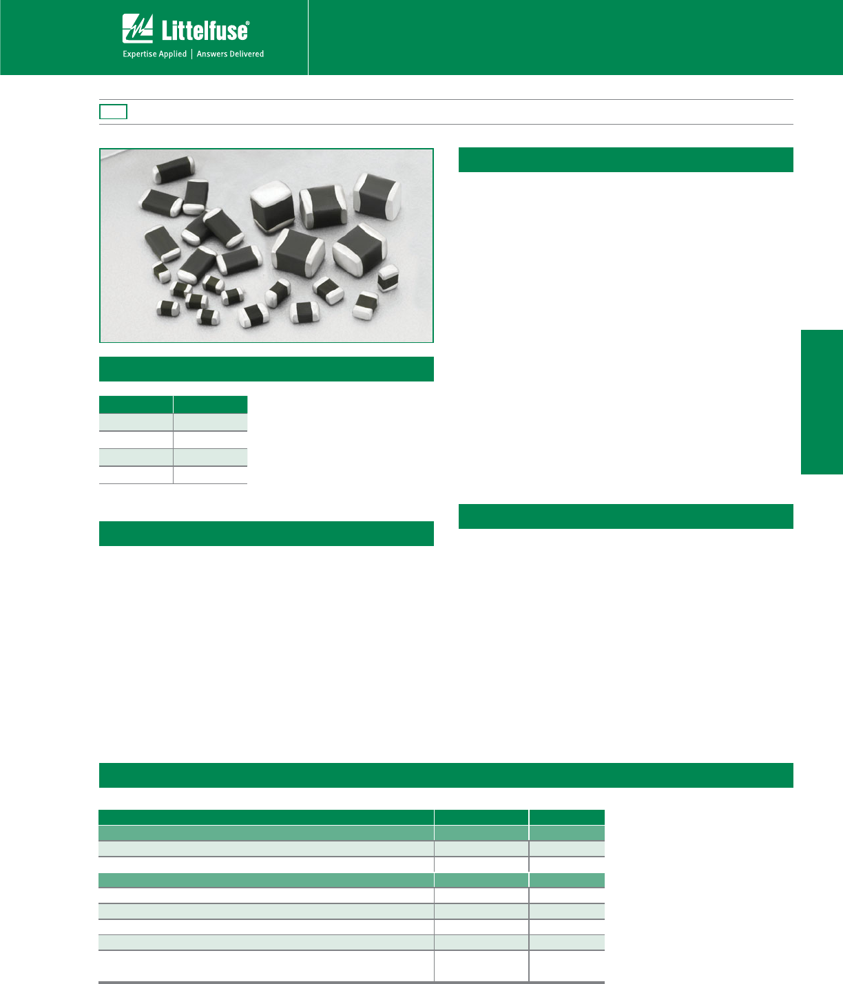
Description
The MLA Automotive Series of transient voltage surge
suppression devices is based on the Littelfuse Multilayer
fabrication technology. These components are designed
to suppress a variety of transient events, including those
specified in IEC 61000-4-2 or other standards used for
Electromagnetic Compliance (EMC). The MLA Automotive
Series is typically applied to protect integrated circuits and
other components at the circuit board level.
The wide operating voltage and energy range make the
MLA Automotive Series suitable for numerous applications
on power supply, control and signal lines.
The MLA Automotive Series is manufactured from
semiconducting ceramics, and is supplied in a leadless,
surface mount package. The MLA Automtove Series
is compatible with modern reflow and wave soldering
procedures.
It can operate over a wider temperature range than Zener
diodes, and has a much smaller footprint than plastic-
housed components.
Features
t "&$2DPNQMJBOU
t 3P)4DPNQMJBOU
t -FBEMFTT
1206 and 1210 chip sizes
t .VMUJMBZFSDFSBNJD
construction technology
t ¡$UP¡$
operating temp. range
t 0QFSBUJOHWPMUBHFSBOHF
V
M(DC)
7UP7
t 3BUFEGPSTVSHF
DVSSFOUYT
t 3BUFEGPSFOFSHZ
YT
t *OIFSFOUCJEJSFDUJPOBM
clamping
t /PQMBTUJDPSFQPYZ
packaging assures
better than UL94V-0
flammability rating
t 4UBOEBSEMPX
capacitance types
available
Applications
t 4VQQSFTTJPOPG
inductive switching
or other transient
events such as EFT
and surge voltage at
the circuit board level
t &4%QSPUFDUJPOGPS*&$
61000-4-2, MIL-STD-
DNFUIPE
and other industry
specifications
t 1SPWJEFTPOCPBSE
transient voltage
protection for ICS
and transistors
t 6TFEUPIFMQBDIJFWF
electromagnetic
compliance of
end products
t 3FQMBDFMBSHFSTVSGBDF
mount TVS Zeners in
many applications
Size Table
Metric EIA
2012
1206
1210
Absolute Maximum Ratings
For ratings of individual members of a series, see device ratings and specifications table.
Continuous MLA Auto Series Units
Steady State Applied Voltage:
%$7PMUBHF3BOHF7
M(DC)
) UP V
"$7PMUBHF3BOHF7
."$3.4
) UP V
Transient:
/PO3FQFUJUJWF4VSHF$VSSFOUμs Waveform, (I
TM
) VQUP A
/PO3FQFUJUJWF4VSHF&OFSHZμs Waveform, (W
TM
) UP J
0QFSBUJOH"NCJFOU5FNQFSBUVSF3BOHF5
A
) UP ºC
4UPSBHF5FNQFSBUVSF3BOHF5
STG
) UP ºC
Temperature Coefficient (DV) of Clamping Voltage (V
C
) at
Specified Test Current
<0.01 $
Varistor Products
©2010 Littelfuse, Inc.
Revision: December 16, 2010
MLA Automotive Varistor Series
Surface Mount Multilayer Varistors (MLVs) > MLA Automotive Series
Specifications are subject to change without notice.
Please refer to www.littelfuse.com/series/ML.html or MLA.html for current information.
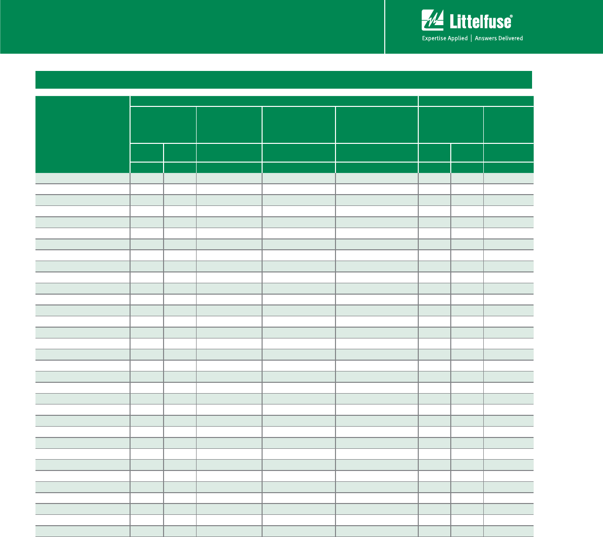
Device Ratings and Specifications
Part Number
Maximum Ratings (125º C)
Specifications (25ºC)
Maximum
Continuous
Working Voltage
Maximum Non-
repetitive Surge
Current (8/20μs)
Maximum
Non-repetitive
Surge Energy
(10/1000μs)
Maximum Clamping
Voltage at 1A (or as
Noted) (8/20μs)
Nominal Voltage
at 1mA DC Test
Current
Typical
Capacitance
at f = 1MHz
V
M(DC)
V
M(AC)
I
TM
W
TM
V
C
V
/%$
Min
V
/%$
Max
C
(V) (V) (A) (J) (V) (V) (V) (pF)
7.-"/)"650 0.100
7.-"/)"650 120
7.-"-/)"650 40 0.100
7.-"/)"650 100 6000
7.-"/)"650 4.0 0.100
7.-"/)"650 4.0 120
7.-"-/)"650 4.0 40 0.100 400
7.-"/)"650 4.0 0.400
7.-"/)"650 9.0 0.100 11.0 16.0 490
7.-"-/)"650 9.0 40 0.100 11.0 16.0
7.-"-/)"650 12.0 9.0 40 0.100 29.0 14.0 410
7.-"/)"650 14.0 10.0 0.100
7.-"/)"650 14.0 10.0 120
7.-"-/)"650 14.0 10.0 40 0.100
7.-"/)"650 14.0 10.0 0.400 1400
7.-"/)"650 14.0 0.100 22.0 120
7.-"/)"650 14.0 120 44.0 22.0
7.-"-/)"650 14.0 40 0.100 44.0 22.0 290
7.-"/)"650 14.0 0.400 44.0 22.0
7.-"/)"650 14.0 BU 22.0 1440
7.-"/)"650 26.0 20.0 0.100 60.0 110
7.-"/)"650 26.0 20.0 100
60.0 220
7.-"-/)"650 26.0 20.0 40 0.100 60.0 140
7.-"/)"650 26.0 20.0 0.600 60.0 600
7.-"/)"650 26.0 20.0 1.200 BU 1040
7.-"/)"650 0.100 46.0 90
7.-"-/)"650 0.100 46.0 90
7.-"/)"650 1.200 BU
7.-"-/)"650 220 0.900 BU
7.-"/)"650 26.0 49.0
7.-"/)"650 42.0 92.0 46.0 60.0
7.-"/)"650 40.0 1.200 BU
7.-"-/)"650 40.0 220 0.900 BU
/05&4
h-hTVGmYJTBMPXDBQBDJUBODFBOEFOFSHZWFSTJPO$POUBDUZPVS-JUUFMGVTFTBMFTSFQSFTFOUBUJWFGPSDVTUPNDBQBDJUBODFSFRVJSFNFOUT
5ZQJDBMMFBLBHFBU$μ"NBYJNVNMFBLBHFμA at V
M(DC)
"WFSBHFQPXFSEJTTJQBUJPOPGUSBOTJFOUTGPSBOETJ[FTOPUUPFYDFFE888BOE8SFTQFDUJWFMZ
Varistor Products
©2010 Littelfuse, Inc.
Revision: December 16, 2010
MLA Automotive Varistor Series
Surface Mount Multilayer Varistors (MLVs) > MLA Automotive Series
Specifications are subject to change without notice.
Please refer to www.littelfuse.com/series/ML.html or MLA.html for current information.
MLA Auto Series
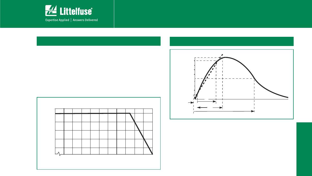
Peak Current and Energy Derating Curve
When transients occur in rapid succession, the average
power dissipation is the energy (watt-seconds) per pulse
times the number of pulses per second. The power so
developed must be within the specifications shown
POUIF%FWJDF3BUJOHTBOE4QFDJmDBUJPOT5BCMFGPSUIF
TQFDJmDEFWJDF'PSBQQMJDBUJPOTFYDFFEJOH¡$BNCJFOU
temperature, the peak surge current and energy ratings
must be derated as shown below.
100
80
60
40
20
0
-55 50 60 70 80 90 100 110 120 130 140 150
PERCENT OF RATED VALUE
AMBIENT TEMPERATURE (
o
C)
T
1
T
2
100
50
0
O
1
TIME
PERCENT OF PEAK VALUE
T
Peak Pulse Current Test Waveform for Clamping Voltage
0
1
7JSUVBM0SJHJOPG8BWF
55JNFGSPNUPPG1FBL
T
1
3JTF5JNFY5
T
2
= Decay Time
Example 'PSBOμT$VSSFOU8BWFGPSN
μs = T
1
3JTF5JNF
20μs = T
2
= Decay Time
Figure 1
Figure 2


