Product Description
Features
MWDMG0050 Series Min Typical Max Unit
Pass Channel Wavelength Range λ1 1465 1515 nm
Reection Channel Wavelength Range λ2
1540 1575
nm
Insertion Loss *
Pass Channel @ λ1
Reect Channel @ λ2
0.7
0.5
dB
Isolation
Reect Channel @ λ1
Pass Channel @ λ2
12
30
dB
Passband Ripple 0.30 dB
Directivity 50 dB
Return Loss 50 dB
Polarization Dependent Loss 0.1 dB
Polarization Mode Dispersion 0.05 ps
Maximum Power Handling 500 mW
Fiber Type Corning SMF-28
Operating Temperature 0 to +70 °C
Storage Temperature -40 to +85 °C
Package Dimensions
**
250 μm Bare Fiber
900 μm Loose Tube
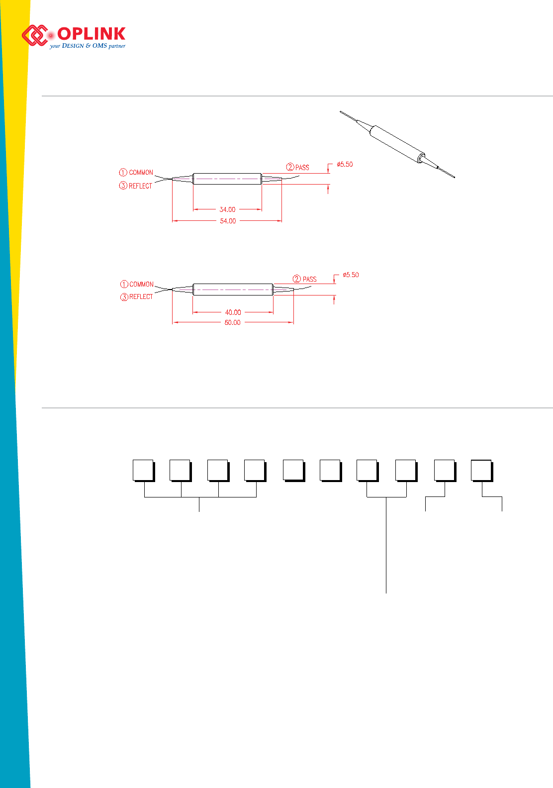
P1: (ø) 5.5 x (L) 34.0
P2: (ø) 5.5 x (L) 40.0
mm
Applications
Performance Specificationns
Note:
* Values are referenced without connector loss.
** The mechanical tolerance should be +/-0.2 mm on all package dimensions unless otherwise custom speci-
ed.
R03.20081117
Green
(1480 nm Plus Supervisory)/
1550 nm Micro-Optic WDM
MWDMG0050 Series
Oplink’s Micro-Optic Wavelength Division Multiplexer (MWDM) is based on
thin-lm lter technology and patented athermal platform for optical device. The
MWDM device is used to combine (or separate) 1550 nm signals with (or from) a
1480 nm pump signal plus the1510 nm supervisory channel. This device offers very
at and wide passband, low insertion loss, and high isolation which makes it ideal
for amplication, telecommunications and WDM network applications. Oplink
MWDM devices are Bellcore GR-1221 qualication tested and complied with
industry green initiatives such as Rohs and WEEE. All Oplink products are epoxy-
free in the optical path.
Environmental Green Plan
Compliance
Wide Operating Wavelength Range
Low Insertion Loss
High Channel Isolation
Ultra Flat Wide Passband
Highly Stable & Reliable
Epoxy-free Optical Path
Fiberoptic Ampliers
System Monitoring
Fiberoptic Instruments
Laboratory R&D
46335 Landing Pkwy Fremont, CA 94538 Tel: (510) 933-7200 Fax: (510) 933-7300 Email: Sales@Oplink.com • www.oplink.com
MWDMG
Ordering Information
Product Lines: Mux/Demux Switching/Routing Coupling/Splitting Monitoring/Conditioning Amplication Transmission Interconnect RGB Laser Modules
Mechanical Drawing / Package Dimensions (dimension in mm)
P1: 250 µm bare ber
P2: 900 µm loose tube
Oplink can provide a remarkable range of customized optical solutions. For detail, please contact Oplink’s OEM
design team or account manager for your requirements and ordering information (510) 933-7200.
000500
Package & Fiber Jacket
P1 + 250 μm bare ber = 11
P2 + 900 μm loose tube = 22
Wavelength
Fiber Length*
1500 nm pass = 0050
0.5 meter = H
1.0 meter = 1
1.5 meters = 5
2.0 meters = 2
Connector Type
None = 1
FC/PC = 2
FC/SPC = 3
FC/APC = 4
SC/PC = 5
SC/SPC = 6
SC/APC = 7
ST = 8
LC = 9
MU = A
Green
(1480nm Plus Supervisory)/
1550nm Micro-Optic WDM
MWDMG0050 Series
R03.20081117
* The tolerance of ber length is +/-0.1m. 1 meter is standard.
The lead-time for special ber length will be longer.


